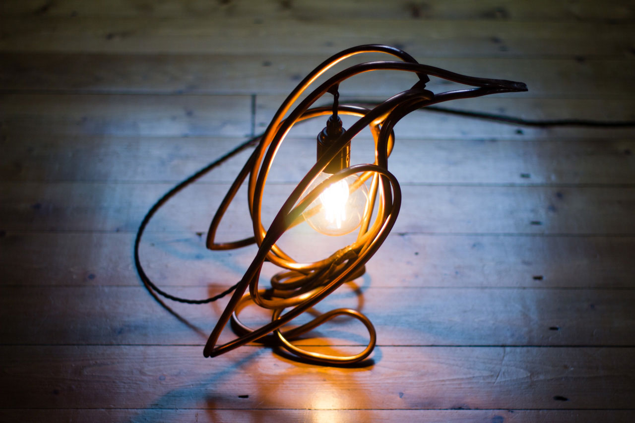
Penguin Lamp
linkUpdate: I've started selling as Quieter on Etsy. Head there now to buy or commission a penguin lamp or two.
I will also be expanding with a selection of prints and digital downloads (abstract scenes and glitch art) in the not-too-distant future. More on those soon.
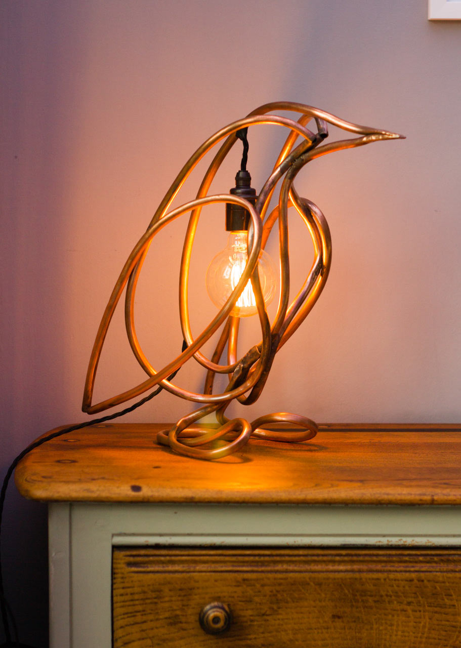
This was something a bit new for me. A project that involved no programming. In short, I made this...
Diversification
After many years of being "just" a programmer, I'm trying to break away from that comfort zone.
Making things, being creative, and experimenting, has always been the most enjoyable part of my work, but more often than not I would have to do those things in my own time. So in my day-job I had ended up in a bit of a rut, and it took me a while to realise that my "I'm just a programmer" outlook was holding me back.
By working closely with talented artists and designers over the years, I had inadvertently immersed myself in a world of creativity and learnt much more than just how to make websites or apps.
Up to now everything I've worked on professionally has been in the digital domain, and I'm far from done with digital - it is a wonderful place to work. But after a while, you end up wanting to make something real, something that won't stop working in a few months when there's a software update.
I don't think it's an uncommon thought for digital creatives though. After speaking to friends and colleges about it there definitely seems to be a consensus on how rewarding it is to create physical objects. Something you can touch. Something lasting.
A lamp
I don't remember exactly why, but earlier this year I started looking at lighting, sculpture, and upcycling, with a general thought to construct something useful from bits of junk, scrap, or any interesting parts I found.
Not long after that I ended up offering to make a lamp as a gift for a friend, Clair, who *really* likes penguins. To give me an idea of the kind of thing she had in mind, she sent me a picture of a table lamp made from a few sections of pipe. Something like this.
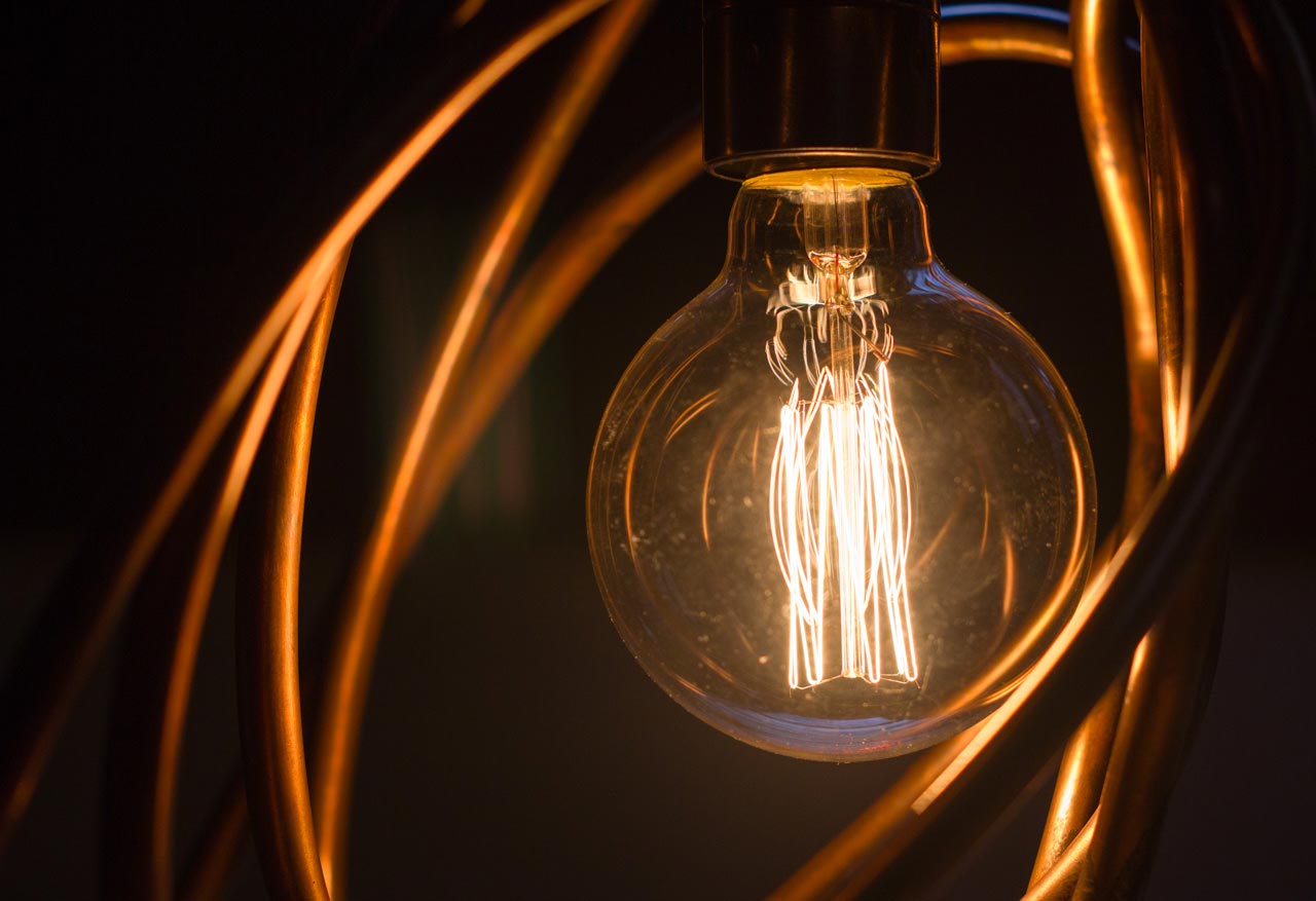
The combination of an Edison style filament bulb and some industrial piping seems to be quite popular at the moment. It was the ideal project for me, and I couldn't say no.
Though I didn't want to make a regular looking lamp. I wanted it to mean something, and thought that something penguin-y would be perfect in this case. I could bend some copper pipe into a the shape of penguin and add a light somewhere... right?
I didn't know if I could do it, and knew nothing useful about sculpture or metalwork. But thought it should work if I broke it down into small tasks and learnt how to do things as I went.
Design
First things first - I had to design something that looked like a penguin and would be simple enough to make. Deciding to use copper piping meant the design had to be kept simple, made of smooth, flowing curves.
The design process involved looking at a lot of reference material (photos of penguins in profile and portrait) and sketching out rough outlines before refining and stylising (mostly just simplifying curves and tweaking positions until I was happy). I started in 2D, making a nice looking penguin profile from three separate spline loops; A wing, the side of the body, and a central core that forms the back and loops around to end at the beak.
I don't really consider myself a designer, so it feels a little weird to be talking about a design process. To me, designers and artists are people with the magical ability to make the things in their head emerge directly from their fingertips. I find it hard to do that; the path from brain to page is slower with more trial and error, iteration, and refinement. Anyway, I've used 3D applications like Blender and Cinema 4D on and off over the years, and felt comfortable enough with the basics to try and make something simple using spline curves to define a shape in 3D.
Working with the profile, I started moving points along the z-axis to give the some depth to the curves for the wings and body sides; The left and right parts are clones of each other that are mirrored along the central axis. The refining (or moving things about) phase was lengthy, I was spinning the model and tweaking positions for quite a while.
While this was going on, I was also looking into how I could actually make it, and what kind of pipe I would use. I settled on 10mm copper tubing, which is thin enough to be bent by hand, while being thick enough to support a small structure like this without issue. Earlier versions of the design used two sizes of pipe, 10mm and 15mm, but during some initial tests I found the 15mm a bit too tricky to bend as tightly I needed without kinking.
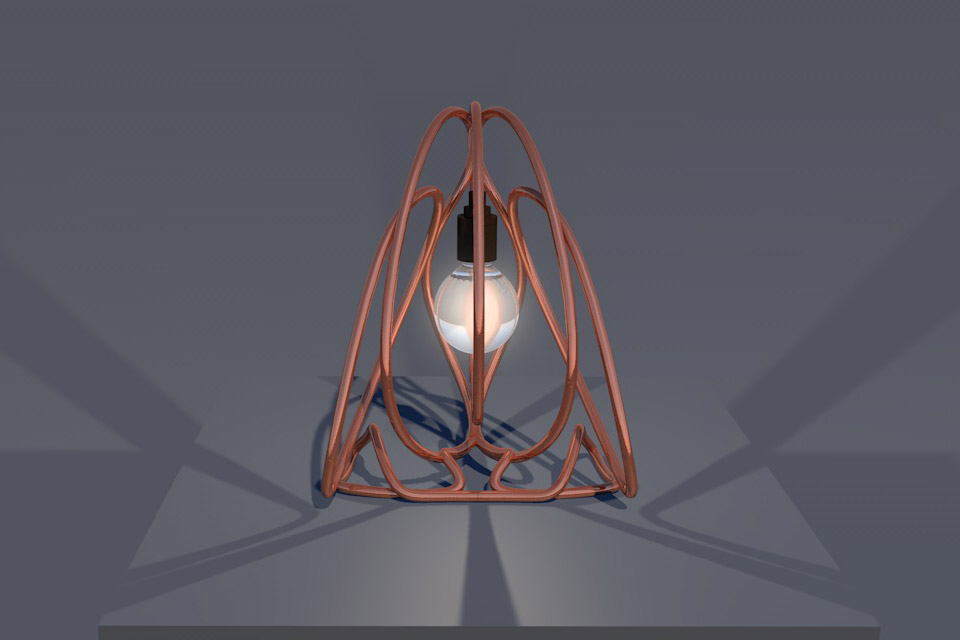
Knowing the diameter of the pipe I'd be using I extruded the splines into pipes, and re-scaled the model. The physical size of the object was determined by the size of the light-bulb I wanted to use, the shape and diameter of the pipes, and the need for a few of the pipe edges to be touching so everything could be joined together. I made some test renders to check how things looked from multiple angles and get an idea of how it might look when lit.
I'd return to the design later to make some more edits after realising a couple of the curves had to be made simpler, and the feet had to be rethought slightly.
Research and development
With the design all-but complete I had to work out how to transfer those on-screen curves into real world objects. First of all, I needed a way to reliably reproduce the curves - to have some guide structures to act both as a reference, and to help shape the pipe. After a brief detour into some cool tube bending robots, I soon found myself learning a bit about plumbing, metalwork, and sculpture on YouTube.
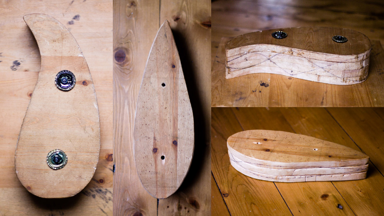
I decided to make wooden forms to bend the pipe around. The left and right curves both have a depth to them, so the templates need to be able to represent them in 3D. I printed off a top-down view of each curve and used the side views (left, right, front, back) to record vertical positions along each line as it winds around the perimeter of the shape. With the 2D templates and the vertical position data I would be able to draw guide lines around the wooden shapes later on.
The final forms are made of a few layers of wood (a shelf from an old wardrobe) cut to the shape of the template, and glued together to form a stack that's deep enough to to contain the depth of the curve.
I cut out the first part using a handsaw and chisel - which was slow going. Luckily a friend happened to mention he had a jigsaw I could borrow, so the remaining parts were much speedier to produce (thanks Tom). After gluing the layers together there was a bit of trimming and sanding before I was happy with the shapes and could draw the guides around the outside edge.
Since the left and right sides of the body and wing are mirror images of each other, I could use the same shape for left and right and just invert the vertical position of the guides drawn around the edge of the form.
Next I needed to bend pipes into loops, join them, and attach them to one another.
Working the pipe
Copper is a pretty forgiving metal to work with, and I enjoyed learning how to get the best out of it. That said, it's definitely an ongoing process. I'm going to keep finding things to improve on, do differently, or more efficiently, for a while yet.
I bent the pipe by hand with the aid of a pipe-bending spring (a steel spring that slides over the outside of the pipe to help it keep a circular cross-section while bending) for the tighter curves. Bending each part was quite a time intensive process, with lots of checking against the template, bending, and rechecking.
After I'd completed a few, I realised there was little chance of me making perfectly symmetrical parts; a few millimetres of error here and there soon adds up over the course of a curve. It was a concern at the time - I like to perfect things - but I came to realise that as long as the parts are similar enough, any small differences will only add to the personality and uniqueness of the finished piece.
Assembly
Joining copper-to-copper isn't trivial, but it is a lot easier than for some other metals. It has quite a low melting point, and can be brazed in air using a propane torch. So it's fairly accessible to anyone willing to watch some YouTube and venture into a DIY store.
Each piece was first joined into a single, sturdy, loop by filing the ends until they sat flush together, and brazing the joint. The centre loop closes at the beak, which was made by hammering the two ends of pipe together and brazing the join between them.
Assembling the main structure was a bit trickier, but still a fairly straight-forward set of steps. Starting with the central loop, I attached the left and right body parts followed by each of the wings. To braze the pipes together they needed to be held securely in position. After slightly flattening and cleaning the contact areas on each pipe, I secured them into position with a combination of some scrap wood to prop things up and some steel picture-wire to firmly tie them together.
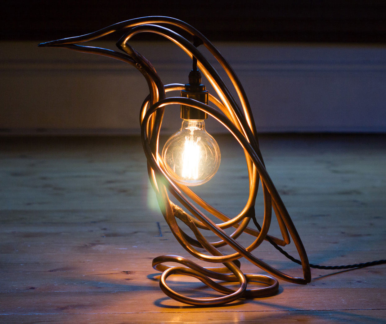
Attaching one part at a time, a penguin shape slowly emerged from the pipes, and I could begin to see if what I was making was anything like the design. I was pleasantly surprised by how it had turned out, I didn't really expect it to work so well, but from here on had a much better idea of how it would look when complete.
Feet
While bending the other parts, I realised that the original design I had for the feet was too intricate and would be impossible to make with the pipe I was using. I was also slightly concerned that - unlike the other parts - I'd have to bend it by eye, from a single length of pipe, in a symmetrical design.
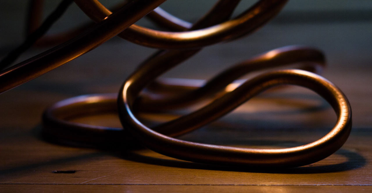
After reworking and simplifying the design I had a much better idea of how the feet could both look the part, and act to support everything else. The feet are made of a single loop of pipe with left and right lobes for each foot, the two ends of the pipe come together in the middle to join to the bottom of the main body.
I thought they would look good and support the body, but didn't know if it would all balance; I needed the body to be held at a certain position so the bulb would hang down in the centre. By suspending it from different points along the back, I found where it balanced at the right angle, and marked that position for later.
Holding the body in position where the feet would attach, I tried to judge the forces involved in supporting and balancing the rest of the body. With left and right feet there's little chance of it toppling sideways, but there is a tendency for it to tip forward. However, I thought I could add some extra ballast inside the pipes at the bottom if needed later on.
Starting with a straight length of pipe I marked the centre and two points at equal distances either side of that to show where to start forming each foot. From there it was a case of slowly bending each side and checking positions in relation to the bottom of the body. It took quite a while, but once I was happy with the feet I trimmed off the excess pipe at the ends and hammered them together into a single flat-ish shape that curves up to meet the bottom of the body.
After attaching the feet I gently bent the supports to adjust the angle a little. Once I was happy with it, it did balance but was a little front-heavy so would tip quite easily if pushed. I had already sealed up the feet tubes, so I added some weight in the form of ball-bearings inside the bottom of the wing sections.
Lighting
I wanted the wire to enter at the top of the spine above the bulb, and follow the back to exit at the bottom. I used the balance position I marked on the back earlier for the top hole, and judged the position of the 'tail' hole by eye.
It was a little awkward cutting out sections from the middle loop with everything else assembled. But, after a bit of tricky filing, the wire would pass through and I was happy with the result. Though it would have been easier to make the holes earlier on in the build, I needed to see the final shape to be able to place them.
The lamp has a black 3-core braided fabric cord with an in-line switch added to toggle the power. There's some black electrical tape around the cord to protect it where it enters and exits the holes cut in the pipe, and it's sealed into position at each end with some black Sugru.
Finishing touches
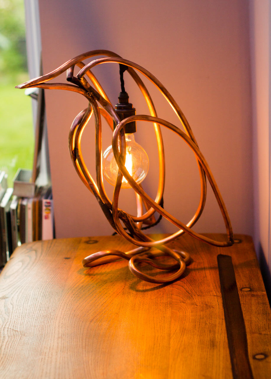
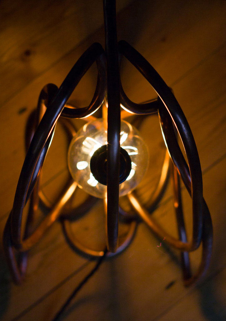
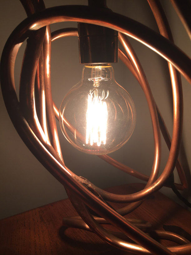
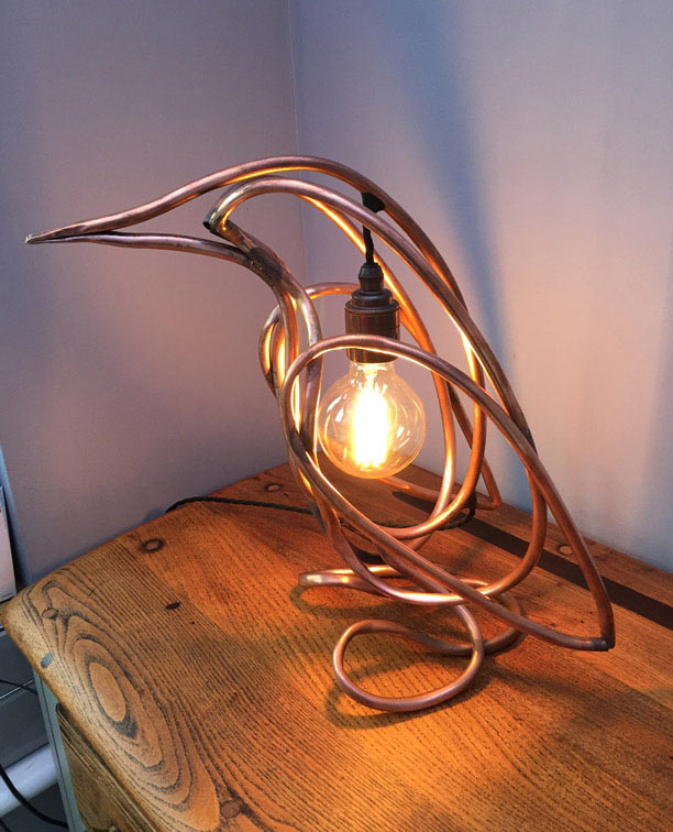
Fingerprints, sweat, grease, and dirt will quickly dull the surface of copper, but a quick polish with some steel wool gives it a nice shine after a lot of handling. After that, all that was left to do was put the bulb in and take some pictures before packing it up for delivery.
I'm really happy how it turned out. It was a fun, if time consuming, thing to build, and I have started making more.
I don't think I would have tried to make something like this if it wasn't for Clair's request, and since completing and delivering it she's been very complimentary and more than happy with the result.
The photos of the lamp at the top of the page, and the three below were taken by its new owner - thank you Clair.
Next
I'm making more penguin variations, which will be are for sale, and I'll probably start working on some other designs too.
So do get in touch if you want a unique handmade penguin lamp of your own.