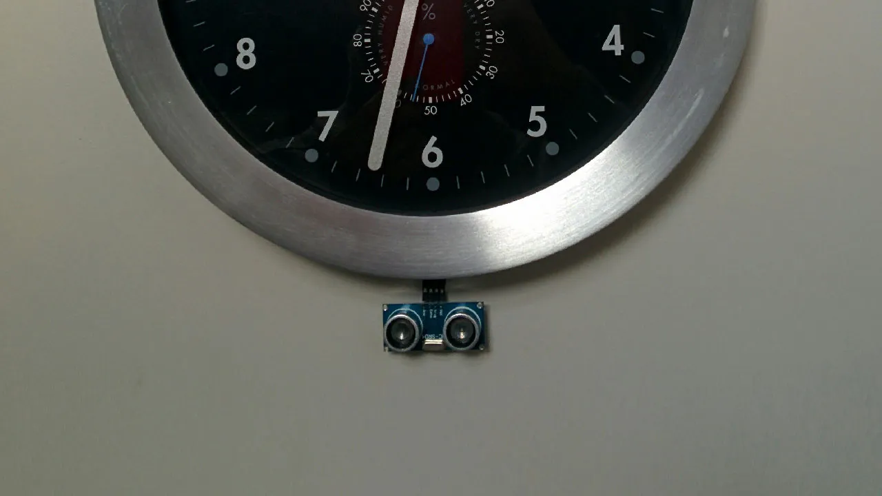
The origins of this project were pretty simple… I had an ultrasonic distance sensor, wrote some code (opens in a new tab) to use it, and thought this would be a good way to test it out. I was having fun learning Arduino and had previously experimented with rewiring and controlling clock mechanisms, so why not stick the two together?
The clock control is based on the method shown here (opens in a new tab), and involves soldering a couple of wires onto the existing circuit so that Arduino can be used to replicate the motor pulses to drive it.
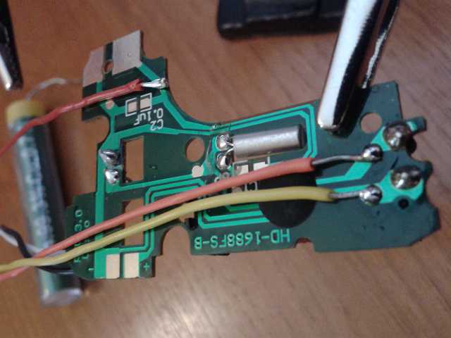
For some reason I wanted to be able to run the clock normally too, so didn’t cut any tracks and added extra wires to pass in power to the full circuit (the original battery connections had to be severed for the modifications so I couldn’t use them, but there happened to be some unused power connections on the PCB that could be used instead).
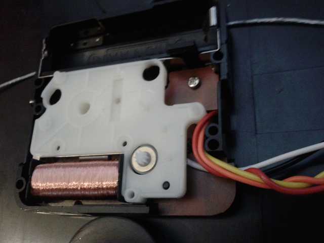
The modified board fitted snugly when returned to the enclosure, and a section at the edge of the plastic case was cut away to provide a small exit hole for the wiring to fit through once the cover was replaced.
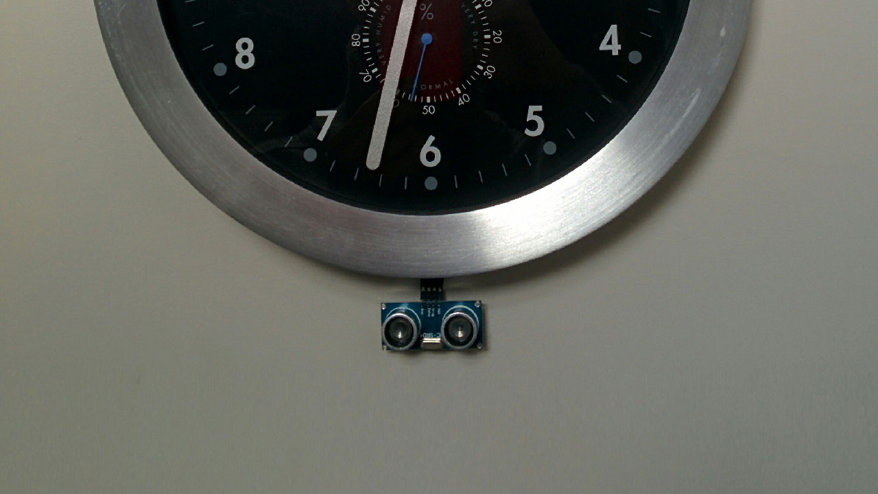
The distance sensor was connected up and ‘mounted’, dangling below the clock face, pointing out hoping to detect anyone that passed by. Power was supplied by an extra (larger) battery pack fixed to the back.
The performance and behaviour of the clock is not too bad, but could certainly be improved. Power consumption is (unsurprisingly) quite a bit higher than on the unmodified clock, and the second hand can occasionally take a couple of tries to fully tick onto the next position.
I think either: transitioning from one tick-rate to another causes issues with the mechanical movement of the mechanism, or it’s down to timing issues with the motor pulses themselves.
Making rate changes more slowly could help things stabilise a bit if the mechanism doesn’t like rapidly changing rate, or if pulse timing is a problem it might be better to control an external timer that generates a stable clock pulse directly on the PCB to replace the oscillator that drives the IC on the board.
I might try those improvements later on, but most likely on a different project.